Annotated PDF: ceno-2024-387.pdf (Note: older version of the paper) Link
General Idea:
- Group the execution trace by opcode
- Prove all opcodes of the same type in a data-parallel fashion using parallel GKR instances of variable size
While this system was designed with GKR in mind, the core concepts translate to other prove systems (e.g. they mention Plonky2 in the discussions).
GKR Circuit Structure
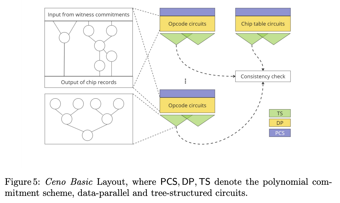
This Figure describes the structure of the circuits:
 There is one layered arithmetic circuit for each instruction, consisting of three parts:
- Input Layer: For each execution of the given instruction, the committed data needed to execute it including:
- A input state record , to denote the value of the program counter, clock and stack pointer before the instructions
- Additional witness data needed to prove correct execution (this depends on the instruction)
- Opcode circuits: A small layered circuit repeated many times (in a data parallel fashion) to compute:
- The output state record
- Any other values that need to be written to the “bus”. For example:
- For memory and stack, they use Offline Memory Checking
- For lookups, they use LogUp (LogUp & cq), so any expressions on the LHS / RHS of the lookup would be computed here
- Tree-structured circuit: A binary tree of logarithmic depth needed to compute updates to the “bus”.
- This could be either doing a Permutation Check via Product Check (= multi-set equality check) or compute a sum of fractions as needed in LogUp (see LogUp & cq)
- The output will be single (extension field) value that will be known to the verifier
- For example, a verifier can validate that → This ensures that all operations are executed in the right order!
The chip table circuit (if I understood this right) is responsible for initializing and finalizing memory (see Offline Memory Checking).
Put in PIL
In my understanding, this could be expressed in PIL using one machine per instruction and no “main” machine.
Ignoring the stack pointer (not needed for a register machine), this would look somewhat like this.
// Need to commit to the input state record
col witness pc_in, clk_in;

// Assert that the current opcode matches the current
// by "sending" a tuple to the bus with multiplicity 1.
// This is analogous to doing something like
// [pc, OPCODE] in [rom.line, rom.opcode]
bus_send((ROM_ID, pc_in, OPCODE), 1);

// Execute the actual instruction, which might involve
// reading from and writing to memory or registers and
// validating additional witness values (e.g. byte
// decompositions)
// ...

// Compute the next PC (which might depend on some
// result of the computation, or just be pc_in + 1)
col pc_out = ...;

// The clock is just incremented by one
col clk_out = clk_in + 1;

// Receive the tuple (pc_in, clk_in)
bus_receive((STATE_ID, pc_in, clk_in), 1);
// Send the tuple (pc_out, clk_out)
bus_send((STATE_ID, pc_out, clk_out), 1);
There would also need to be a ROM machine that receives the (ROM_ID, pc, OPCODE) tuples with the correct multiplicity.
Note that:
- There is no need for boolean instruction flags. As a result, adding an extra instruction is fairly cheap!
- There are no “next” references, all instructions can be validated completely independent of each other and are only connected via the bus.
- The cost to execute one instruction does not depend on other instructions. For example, if one instruction interacts with many registers, that does not influence cost of other instructions.
- This implementation assumes that
bus_{receive,send}generates the tree circuit. This is not something we can currently express in PIL though, so it would need some kind of built-in.
Ceno Pro
The main advantage of GKR is that the prover does not need to commit to intermediate values of the computation. But most instructions are fairly simple, leading to “shallow” circuits where there are not too many intermediate values.
The idea of Ceno Pro is to summarize blocks of instructions into more complex instructions. Looking at an assembly program, a “basic block” is a sequence of instructions one entry point and one exit point (i.e., only the last instruction is a branch instruction). Commonly executed basic blocks (e.g. the body of a loop) can be proven as one instruction.
Advantages:
- If a basic block interacts with the same register multiple times, only the first and last interaction leads to a bus interaction
- There is only one ROM interaction for the basic block